Land Survey and GIS
All the most necessarily in Land SurveyingLand Survey and GIS
All the most necessarily in Land SurveyingTRAVERSE CALCULATIONS
TRAVERSE CALCULATIONS
PROCEDURE FOR TRAVERSE CALCULATIONS
BALANCING ANGLES OF CLOSED TRAVERSES

ADJUSTING ANGLES
DETERMINING BEARINGS OR AZIMUTHS
LATITUDES AND DEPARTURES
LATITUDES AND DEPARTURES

CLOSURE OF LATITUDES AND DEPARTURES
CALCULATION OF LATITUDES AND DEPARTURES
Station Bearing Length Latitude Departure A N 26° 10'E 285.10 +255.88 +125.72 B S 75° 25'E 610.45 -153.70 +590.78 C S 15° 30'W 720.48 -694.28 -192.54 D N 1° 42'W 203.00 +202.91 -6.02 E N 53° 06'W 647.02 +388.48 -517.41 A MISCLOSURE -0.71 +0.53
CALCULATION OF LATITUDES AND DEPARTURES
Station Azimuth Length Latitude Departure A 26° 10' 285.10 +255.88 +125.72 B 104° 35' 610.45 -153.70 +590.78 C 195° 30' 720.48 -694.28 -192.54 D 358° 18' 203.00 +202.91 -6.02 E 306° 54' 647.02 +388.48 -517.41 A MISCLOSURE -0.71 +0.53
ADJUSTMENT OF LATITUDES AND DEPARTURES

ADJUSTMENT OF LATITUDES AND DEPARTURES
Station Azimuth Length Latitude Departure A +0.08 -0.06 26° 10' 285.10 +255.88 +125.72 B +0.18 -0.13 104° 35' 610.45 -153.70 +590.78 C +0.21 -0.15 195° 30' 720.48 -694.28 -192.54 D +0.06 -0.05 358° 18' 203.00 +202.91 -6.02 E +0.18 -0.14 306° 54' 647.02 +388.48 -517.41 A TOTALS 2466.05 -0.71 +0.53
ADJUSTMENT OF LATITUDES AND DEPARTURES
Balanced Balanced Station Latitude Departure Latitude Departure A +0.08 -0.06 +255.88 +125.72 +255.96 +125.66 B +0.18 -0.13 -153.70 +590.78 -153.52 +590.65 C +0.21 -0.15 -694.28 -192.54 -694.07 -192.69 D +0.06 -0.05 +202.91 -6.02 +202.97 -6.07 E +0.18 -0.14 +388.48 -517.41 +388.66 -517.55 A TOTALS -0.71 +0.53 0.00 0.00
RECTANGULAR COORDINATES
CALCULATING X AND Y COORDINATES

COORDINATES
Balanced Balanced Station Latitude Departure Y-coord X-coord A 10000.00 10000.00 +255.96 +125.66 B 10255.96 10125.66 -153.52 +590.65 C 10102.44 10716.31 -694.07 -192.69 D 9408.37 10523.62 +202.97 -6.07 E 9611.34 10517.55 +388.66 -517.55 A 10000.00 10000.00 TOTALS 0.00 0.00
LINEAR MISCLOSURE

TRAVERSE PRECISION
definition latitude and longitude
Latitude
Longitude
With this saying in my mind, I picture all of the longitudinal meridians meeting at the poles, each meridian the same length as the next.
Symbols for degrees, minutes and seconds:
° | Degrees |
' | Minutes |
" | Seconds |
The three common formats:
| DDD° MM' SS.S" | Degrees, Minutes and Seconds |
| DDD° MM.MMM' | Degrees and Decimal Minutes |
| DDD.DDDDD° | Decimal Degrees |
Degrees, Minutes and Seconds
Degrees and Decimal Minutes
This is the format most commonly used when working with electronic navigation equipment.
![]()
Decimal Degrees
This is the format you'll find most computer based mapping systems displaying. The coordinates are stored internally in a floating point data type, and no additional work is required to print them as a floating point number.
Often the N-S and E-W designators are omitted. Positive values of latitude are north of the equator, negative values to the south. Watch the sign on the longitude, most programs use negative values for west longitude, but a few are opposite. This saves a lazy western hemisphere programmer from having to type in a minus sign before most of their longitude values.
![]()
Which format should you use?
First off, if you are working with other people who have agreed upon a format to use, then you should probably use that format.
Next, you will want to look at the maps, lists of coordinates, and any software you may be using. If you can find a consistent format among them, your work will be easier.
You can set your GPS to display any one of these three formats. Locations can be entered into the GPS with the selected format, and then by switching the display format setting, viewed in a different format.
I frequently choose to use the Degrees and Decimal Minutes format, even though the USGS maps I'm using are marked in Degrees, Minutes and Seconds. The markings on the map are all at either 0, 15, 30, or 45 seconds. By remembering the "quarter minute conversions" of 0.00, 0.25, 0.50, and 0.75, I can quickly do the conversions in my head.
A Quick Guide to Using UTM Coordinates
A Quick Guide to Using UTM Coordinates
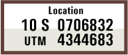
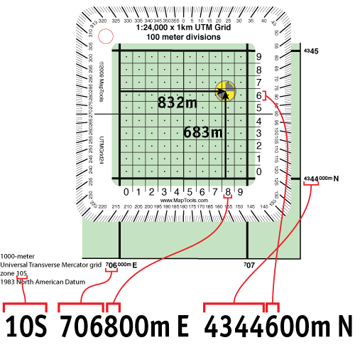
Standing at the center of the marker shown on the map below, a GPS unit set to display position in UTM/UPS format, would report a location of:
Let's look at where the various parts of the UTM position come from on the map.
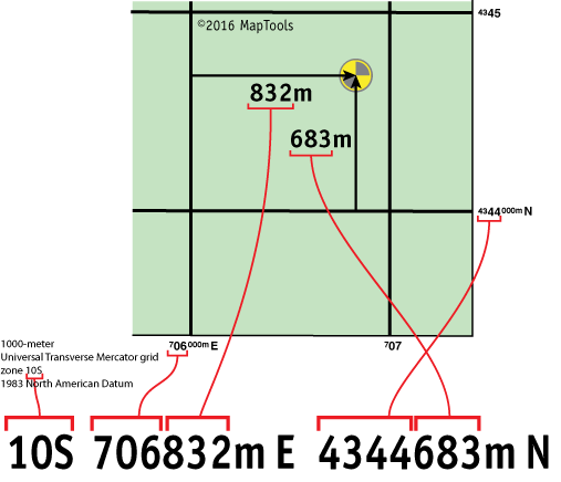
The map has grid lines spaced every kilometer or 1000 meters. The grid is labeled with UTM coordinate values. The vertical grid lines determine East-West position and the horizontal grid lines determine North-South position.
Look along the bottom edge of the map at the labels for the vertical grid lines.
![]()
The 10S is the Grid Zone Designation you are in. The Grid Zone is necessary to make the coordinates unique over the entire globe.
The top set of numbers, 706832, represent a measurement of East-West position, within the Grid Zone, in meters. It's called an Easting. Using a map with a 1000m grid, the first digits are come from the label for the grid line to the west of the position. The last 3 digits are the distance in meters measured from the western grid line.
The bottom set of numbers, 4344683, represent a measurement of North-South position, within the Grid Zone, in meters. It's called a Northing. Using a map with a 1000m grid, the first digits are come from the label for the grid line to the south of the position. The last 3 digits are the distance in meters measured from the southern grid line.
Using various tools to plot and measure UTM positions on a map
Using a grid style tool to plot/measure a UTM position with 100m precision
The precision of the Easting and Northing measurements
A UTM coordinate's Easting and Northing are both distance measurements made in meters. But this leaves us with a dilemma when we have not measured with one meter precision. What to do with the unknown digits. Let's look at the Easting of a point that is 146m east of the western grid line. T hat would, in our example above, give it an Easting of 706146m E. But on a large scale map, no tool will be able to measure to the nearest meter. At best you'll get 10 meters, and if you're eyeballing it you'll be good to get 100m accuracy. But we still have to write all the digits down to the meter. The convention is to fill in the unknown/unmeasured digits with zeros, and to avoid any rounding up. So our easting becomes 706140m E or 706100m E. The trouble is we don't know if the location we are measuring was located with great accuracy at 706100m E, or if we just did a 100m rough measurement and the location could have an easting between 706100m E and 706199m E. One possible solution is to write the Easting an Northing in kilometers, using as many digits after the decimal point as we have measurement accuracy. For more on this idea check out our page on kUTM Coordinates.
For improved clarity, write the measurement units with the Easting and Northing
In the world of map coordinates, there are a lot of different coordinate formats. If you just run a bunch of digits together with no spacing or units, you run the risk of having someone else misunderstand what coordinate format you are using. In the case of UTM, I suggest writing "m E" for "meters East" after the Easting, and "m N" for "meters North" after the Northing. When communicating a coordinate by voice, say the words "meters East" after the Easting and "meters North" after the Northing.
There are several documented cases where a string of digits was passed, usually by voice, to someone else who misinterpreted the coordinate format. In one case this led to the rescue helicopter being sent 30 miles away from the actual incident.
More details about UTM Grid Zones
More details about UTM Grid Zones
The world's 60 UTM zones
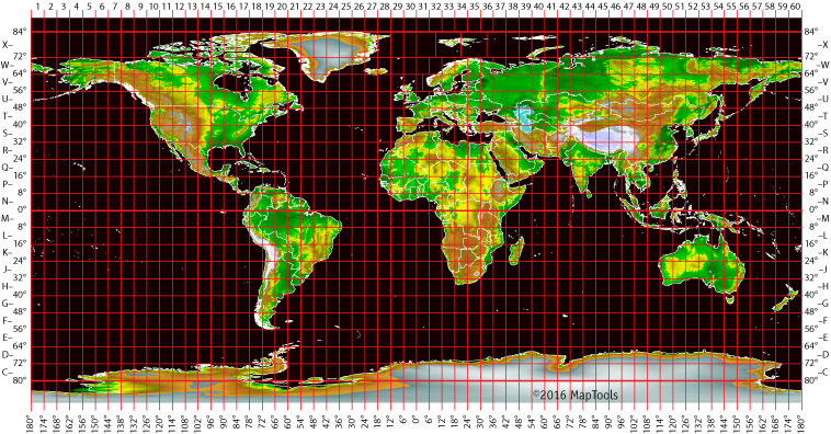
The UTM coordinate system divides the earth into 60 zones each 6 degrees of longitude wide. These zones define the reference point for UTM grid coordinates within the zone. UTM zones extend from a latitude of 80° S to 84° N. In the polar regions the Universal Polar Stereographic (UPS) grid system is used. Note that there are a few exceptions to zone width in Northern Europe to keep small countries in a single zone.
UTM zones are numbered 1 through 60, starting at the international date line, longitude 180°, and proceeding east. Zone 1 extends from 180° W to 174° W and is centered on 177° W.
Each zone is divided into horizontal bands spanning 8 degrees of latitude. These bands are lettered, south to north, beginning at 80° S with the letter C and ending with the letter X at 84° N. The letters I and O are skipped to avoid confusion with the numbers one and zero. The band lettered X spans 12° of latitude.
Eastings and Northings within a zone
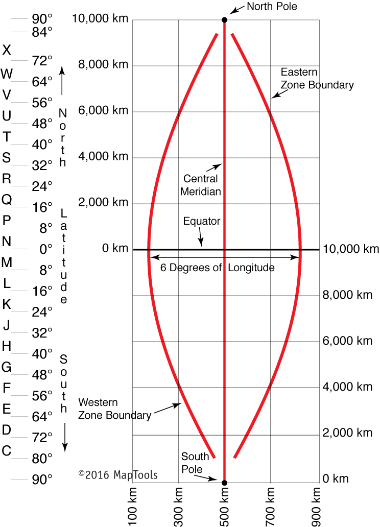
A single grid zone measures about 20,000km tall and only about 700km wide. So the above diagram has been compressed in the vertical axis by about 15X. The eastern and western zone boundaries are truly much straighter.
A square grid is superimposed on each zone. It's aligned so that vertical grid lines are parallel to the center of the zone, called the central meridian.
UTM grid coordinates are expressed as a distance in meters to the east, referred to as the "easting", and a distance in meters to the north, referred to as the "northing".
Eastings
UTM easting coordinates are referenced to the center line of the zone known as the central meridian. The central meridian is assigned an easting value of 500,000 meters East. Since this 500,000m value is arbitrarily assigned, eastings are sometimes referred to as "false eastings"
An easting of zero will never occur, since a 6° wide zone is never more than 674,000 meters wide.
Minimum and maximum easting values are:
160,000 mE and 834,000 mE at the equator
465,000 mE and 515,000 mE at 84° N
(Exceptions to this will be found in the unusual zones in northern Europe.)
Northings
UTM northing coordinates are measured relative to the equator. For locations north of the equator the equator is assigned the northing value of 0 meters North. To avoid negative numbers, locations south of the equator are made with the equator assigned a value of 10,000,000 meters North.
Some UTM northing values are valid both north and south of the equator. In order to avoid confusion the full coordinate needs to specify if the location is north or south of the equator. Usually this is done by including the letter for the latitude band.
If this is your first exposure to the UTM coordinate system you may find the layout of zones to be confusing. In most land navigation situations the area of interest is much smaller than a zone. The notion of a zone falls away and we are left with a simple rectangular coordinate system to use with our large scale maps.
Topographic Survey Requirements
Sanitary Sewer Overflow (SSO) Control
and Wastewater Facilities Program
Topographic Survey
Requirements
City of Baton Rouge/Parish of East Baton Rouge
Department of Public Works
Submitted by
Prepared by: Tim Jett
Reviewed by: Jennifer Baldwin
Approved by: James Hawley
Revision 1
August 2009
MKE/092380086 III REV. 1 / AUGUST 2009
Contents
Section Page
1. Introduction........................................................................................................................1-1
2. General ................................................................................................................................2-1
3. Control Points .....................................................................................................................3-1
4. Survey Limits and Cross Sections...................................................................................4-1
5. Utility Locations .................................................................................................................5-1
6. Deliverables........................................................................................................................6-1
MKE/092380086 1-1 REV. 1 / AUGUST 2009
1. Introduction
This document provides requirements for surveying performed for projects associated with
the City of Baton Rouge/Parish of East Baton Rouge (C-P) Sanitary Sewer Overflow (SSO)
Control and Wastewater Facilities Program. The term Engineer is defined as an engineering
design firm under contract with the C-P and producing engineering design work on the
Program. These requirements are provided to encourage consistency in the design approach
used by various Engineers.
While the purpose of these requirements is to assure uniformity, it is not intended to stifle
Engineer’s creativity, design innovation, and ingenuity. Engineers shall review these
requirements and adopt them for design of the facilities for which they are responsible.
Engineers are ultimately responsible for their design, and this responsibility is in no way
diluted or absolved by these requirements.
It may be necessary for the Engineer to deviate from these requirements. In such cases, the
Engineer shall immediately bring this matter to the attention of the Program Manager (PM)
by completing and submitting the form included in the Program Requirements for Engineers.
The PM reserves the right to allow or disallow the deviation from the requirements. If the
deviation will impact design contract terms, then a Supplemental Agreement will be
negotiated between the Engineer, the PM, and the C-P.
MKE/092380086 2-1 REV. 1 / AUGUST 2009
2. General
The surveyor shall follow the current standards of practice as outlined in the Laws and
Rules of the Louisiana Professional Engineering and Land Survey Board in conducting
surveys. As such, all work shall adhere to modern surveying theory, practice, and
procedures. Surveys shall be performed in English units and all data collected shall be
reduced to state plane coordinates.
If right-of-way or servitude maps are required for the project, they shall be prepared in
accordance with the Program Right-of-Way Map/Real Estate Standards.
MKE/092380086 3-1 REV. 1 / AUGUST 2009
3. Control Points
Horizontal and vertical control points for design, topographic, boundary, and construction
surveys shall meet the accuracy of surveys for a Class A (Urban) Survey as outlined in the
Rules of the Louisiana Professional Engineering and Land Survey Board. Horizontal control
shall be NAD 83 (92) and vertical control shall be NAVD 88. Surveyor shall only use EBR 88
monuments.
As part of the C-P SSO Program, the C-P Department of Public Works (DPW), in
conjunction with the U. S. Army Corps of Engineers, New Orleans District, has established
20 vertical control benchmarks to be utilized for surveying performed as part of the
Program. Information related to these benchmarks including their locations is available on
the Program Web site at www.brprojects.com/sewer/pages/contractor_guidelines.htm.
MKE/092380086 4-1 REV. 1 / AUGUST 2009
4. Survey Limits and Cross Sections
The Engineer shall perform survey work to determine all surface features and at or below
ground elevations at the project site and/or located within the right-of-way along the entire
alignment and other areas as may be necessary to develop plan and profiles and site plans
for the recommended project. The Engineer may choose to utilize Global Positioning System
(GPS) data for mapping of x-y coordinates. The scope of the surveying work shall include,
but not be limited to:
• Determining boundary conditions (site property boundary, temporary and permanent
servitude widths determined, and rights-of-way-widths).
• Confirming existing facilities controls and elevations with current survey and
Establishing additional survey control points where required.
• Identifying mapping options and develop preliminary and/or final design mapping.
• Performing field survey in State Plane Coordinate control. All existing surface features
within the project limits shall be shown. Surface features include, but are not limited to,
edge of pavement, pavement type, curb, gutter, sidewalks, retaining walls, driveways,
parking lots, utility poles, utility towers, overhead electric lines, pavement markings
(including type of pavement marking), traffic lights, traffic signs, all other signs, tree
type and trunk diameter, drainage channels (including invert and water surface
elevations at sewer line crossing), water bodies (ditches, streams, creeks, rivers, ponds,
etc.) including invert and water surface elevations at sewer line crossing, railroads,
structures, bridges, columns, telephone boxes, fences, gates, and all other surface
features. The size and type of all surface features shall be shown.
• Performing phased or final design level mapping.
• Defining legal issues and constraints (ownership’s, zoning, servitudes, etc.).
• Obtaining parcel maps and ownership information within the project limits. Property
corner surveys shall be conducted within the project limits. All existing lot numbers and
plat information shall be shown.
• Field surveying pavement match points (curbs, gutter, sidewalk, pavements, etc.).
• Researching and showing records of existing adjacent public utility systems.
• Plotting all existing utilities (see Louisiana R.S. 38:2223).
• Field surveying and showing on drawings all underground features and utilities within
the project limits. These include, but are not limited to, sanitary and storm sewers,
water, gas, electric, telephone, cable, fiber optic, traffic loops, services (water, sewer, gas,
and all other services), manholes (including top and invert elevation), utility vaults
(including top and invert elevation), valve boxes (water valves, sewer valves, gas valves,
and all other valves, including top and invert elevations), storm inlets (including top and
TOPOGRAPHIC SURVEY REQUIREMENTS
REV. 1 / AUGUST 2009 MKE/092380086
invert elevation), junction boxes (including top and invert elevation), utility
appurtenances, cleanouts, water meters, lift stations (wet wells, dry wells, and aboveground
piping and valves, including top and invert elevations for wet wells and dry
wells and surface drains and centerline elevations for above-ground piping and valves),
septic systems, storage tanks, and all other underground features. The type, size,
alignment, depth, and top and invert elevations of the underground features shall be
noted. Slopes and flow lines shall be noted for existing sewer lines. Materials of
construction of underground utilities shall be provided where available.
• Survey existing building floor elevations at all identified pump station sites. Provide one
XYZ coordinate on flat open ground in the immediate vicinity of each of the identified
existing and proposed pump stations.
If applicable, special areas or elements to be mapped (using GPS data) include:
• Hazardous materials
• Archaeologically important areas
• Wetlands/endangered species
• Flood plains
• Geotechnical exploration drill holes and test pits
MKE/092380086 5-1 REV. 1 / AUGUST 2009
5. Utility Locations
The Engineer shall collect as-built utility drawings and utility inventory from the Program
Manager. The surveyor shall collect all visible utilities and utility markers and show them
on the survey plans. The surveyor shall also call LA One Call and collect location of the
underground utilities as indicated by LA One Call. Surveyor shall submit call or reference
number received from LA One Call to the Program Manager as verification of the request
for utility locations. If additional utility location activities are included in the Project scope,
such as potholing, the surveyor will also include the locations of all utilities located by these
additional activities on the survey plans and profiles, as applicable.
MKE/092380086 6-1 REV. 1 / AUGUST 2009
6. Deliverables
The survey shall include the following deliverables, to be submitted with other design
deliverables, as appropriate.
• Copy of all survey notes and field roll
• Plan and profiles broken into 24 x 36-inch sheets with station and offset to all utility
poles, fire hydrants, building corners, headwalls, and drainage structures
• Vertical profiles showing the existing centerline ground surface above the proposed pipe
or structure, drainage pipes, pipeline crossings, utilities, ditch centerlines, and other
critical information
• AutoCAD drawings, in accordance with the Program CAD Requirements, showing all
collected data in three dimensional coordinates along with the required pen setting files
• Drawing files in pdf format at full size (24 x 36)